Create MCU Independent Embedded Code
One of the struggles in the embedded world is writing software that is reusable in other projects with different microcontrollers. The reason to that is every microprocessor has its own I/O and hardware structures. Good news! you can still write fully portable MCU software with the Porty framework 🙂
What is Porty?
Porty is prepared as a template for a C/C++ project and it provides common interfaces for basic functionalities like GPIO such that editing the files of that framework is enough to port your project to any microcontroller.
What does it offer?
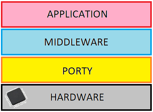
The goal of Porty is to make the application and middleware layers unaware of the MCU hardware. With other words, Porty plays a role as a proxy between the hardware and the application.
 As basic example, you can use
mPinWrite(...) macro to change the value of an I/O without touching any registers or use only the
CLOCK_MHz definition in your timing calculations without worrying about the crystal frequency.
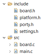
Project files
The given software is an example project for STM32F100 Discovery board and it is supposed to work with other STM32 series without any modification.
 To get the benefit of Porty, you must include
porty.h file from all of your source files and It takes care of other necessary includes for the system to work.
|
1 2 3 4 5 6 7 |
// Includes. #include <stdint.h> #include <stdbool.h> #include <stddef.h> #include "settings.h" #include "platform.h" #include "board.h" |
You can also add your own header to porty.h includes section and stop worrying about their scopes since porty.h is included from every file. Other than that porty.h file has the definitions for CLOCK and basic delay macros. You can safely rely on the CLOCK_xHz values to build your timing.
|
1 2 3 4 5 6 7 8 9 10 11 12 13 14 15 |
// Definitions. #define CLOCK_Hz (CLOCK) ///< MCU clock in [Hz] #define CLOCK_kHz (CLOCK_Hz/1000UL) ///< MCU clock in [kHz] #define CLOCK_MHz (CLOCK_kHz/1000UL) ///< MCU clock in [MHz] #define true 1 #define false 0 #define NULL 0 // Simple blocking delays. #define mDelay_1cyc() mNop(); ///< 1cycle time delay. #define mDelay_2cyc() mDelay_1cyc();mDelay_1cyc(); ///< 2cycle time delay. #define mDelay_4cyc() mDelay_2cyc();mDelay_2cyc(); ///< 4cycle time delay. #define mDelay_5cyc() mDelay_4cyc();mDelay_1cyc(); ///< 5cycle time delay. #define mDelay_8cyc() mDelay_5cyc();mDelay_3cyc(); ///< 8cycle time delay. #define mDelay_10cyc() mDelay_5cyc();mDelay_5cyc(); ///< 10cycle time delay. |
The most important part is the hardware-abstraction macros that are defined in platform.h file. This file is fully microcontroller-dependant and must be edited when porting to other platforms. It is the place where MCU headers are included.
|
1 2 |
// Includes. #include "stm32f10x.h" |
General-purpose section implements macros for the most essential functions like Interrupt and Watchdog.
|
1 2 3 4 5 6 7 8 9 10 11 12 |
// General purpose macros. #ifdef WATCHDOG_ENABLED #define mKickWatchdog() IWDG_ReloadCounter() ///< MCU-specific watchdog reset function. #else #define mKickWatchdog() ///< Watchdog is disabled. #endif #define mNop() __NOP() ///< MCU/compiler specific Nop instruction #define mIntEnable() __enable_irq() ///< MCU/compiler specific #define mIntDisable() __disable_irq() ///< MCU/compiler specific #define mIsIntEnabled() ((__get_PRIMASK() & 0x01) == 0) ///< Check if IntEn before disabling #define mEnterCritical() mIntDisable() ///< Alias for mIntDisable() #define mExitCritical() mIntEnable() ///< Alias for mIntEnable() |
Here you can see the interrupt enable/disable macros. Once this file is prepared, you can use mIntEnable() and mIntDisable() macros in your application code. mIsEnabled() macro returns the status of the interrupt which can be used before disabling to re-enable afterwards or not. Example usage is shown below. (Note that for ARM Cortex-M there is no smarter way of doing this)
|
1 2 3 4 5 |
bool wasIntEnabled = mIsIntEnabled(); mIntDisable(); if(wasIntEnabled){ mIntEnable(); } |
Pin macros part is the other important part. Here you can control the input/output pins easily.
|
1 2 3 4 5 6 7 8 9 10 11 12 13 14 15 16 17 18 19 20 21 |
// Pin macros (dynamic use) #define mPinNum_(port, pin) pin ///< Get pin number/code. #define mPinPort_(port, pin) port ///< Get port handle. #define mPinMode_(port, pin, mode) ((&port->CRL)[pin>=8])=((((&port->CRL)[pin>=8]))&(~(0x0000000F<<((pin&0x07)<<2))))|(mode<<((pin&0x07)<<2));///< Set I/O mode. #define mPinOutput_(port, pin) mPinMode_(port,pin,PINMODE_OUT) ///< Make I/O output. #define mPinInput_(port, pin) mPinMode_(port,pin,PINMODE_INP) ///< Make I/O input. #define mPinAnalog_(port, pin) mPinMode_(port,pin,PINMODE_ANA) ///< Make I/O analog. #define mPinAlternate_(port, pin) mPinMode_(port,pin,PINMODE_ALT) ///< Make I/O alternative. #define mPinRead_(port, pin) (((port->IDR)>>pin)&0x0001) ///< Read I/O value. #define mPinWrite_(port, pin, val) ((&port->BSRR)[val==0])=(0x0001<<pin); ///< Write I/O value. // Pin macros (PORTA,0 compatible) #define mPinNum(portpin) mPinNum_(portpin) ///< Get pin number/code. #define mPinPort(portpin) mPinPort_(portpin) ///< Get port handle #define mPinMode(portpin, mode) mPinMode_(portpin,mode) ///< Set I/O mode. #define mPinOutput(portpin) mPinOutput_(portpin) ///< Make I/O output. #define mPinInput(portpin) mPinInput_(portpin) ///< Make I/O input. #define mPinAnalog(portpin) mPinAnalog_(portpin) ///< Make I/O analog. #define mPinAlternate(portpin) mPinAlternate_(portpin) ///< Make I/O alternative. #define mPinRead(portpin) mPinRead_(portpin) ///< Read I/O value. #define mPinWrite(portpin, val) mPinWrite_(portpin,val) ///< Write I/O value. |
Although the macros seem like re-declaration, there are 2 types of macros here.
|
1 2 |
#define mPinWrite_(port, pin, val) ((&port->BSRR)[val==0])=(0x0001<<pin); #define mPinWrite(portpin, val) mPinWrite_(portpin,val) |
The ones with trailing underscore are the real macros that you need to modify for your platform, and the ones without underscore are to enable the usage of PORT,PIN style pin definitions (that are defined in board.h file). Here mPinWrite(LED_Green, 1) expands PORT,PIN into 2 parameters and calls mPinWrite_(GPIOC, 9, 1) with 3 parameters.
|
1 2 3 4 |
// Pin definitions. #define LED_Green GPIOC,9 #define LED_Blue GPIOC,8 #define BUTTON_User GPIOA,0 |
Board definitions file board.h also includes Interrupt priority settings and other MCU-related stuff.
|
1 2 3 4 |
// IRQ priorities (HIGHEST 0..15 LOWEST). #define IRQPRIORITY_ADC1 1 #define IRQPRIORITY_TIM4 4 #define IRQPRIORITY_DMA1CH1 5 |
All the global settings goes into settings.h file.
|
1 2 3 |
// Settings. #define CLOCK (8000000UL) ///< MCU clock in [Hz] #define WATCHDOG_ENABLED ///< Watchdog enabler switch. |
Finally the only C file, board.c has board-related initializer function Board_Init() . You must call this in the beginning of your main.c and put all hardware related initialization code in this function.
|
1 2 3 4 5 6 7 8 9 10 11 12 13 14 15 16 17 18 19 20 21 22 23 24 25 26 27 28 |
/** * @brief This is MCU/board-specific peripheral initializer. */ void Board_Init(void){ SystemCoreClockUpdate(); // Enable peripheral clocks. RCC_APB2PeriphClockCmd( RCC_APB2Periph_AFIO | RCC_APB2Periph_GPIOA | RCC_APB2Periph_GPIOB | RCC_APB2Periph_GPIOC | RCC_APB2Periph_GPIOD | RCC_APB2Periph_GPIOE | RCC_APB2Periph_GPIOF | RCC_APB2Periph_GPIOG , ENABLE); // Output pins. mPinOutput(LED_Green); mPinOutput(LED_Blue); // Input pins. mPinInput(BUTTON_User); // ADC pins. //... } |
Blinky example
Now its time to demonstrate Porty with the most basic LED blinking example.
|
1 2 3 4 5 6 7 8 9 10 11 12 13 14 15 16 17 18 19 20 21 22 23 24 25 26 27 28 29 30 31 32 33 34 35 36 37 38 39 40 41 42 43 44 45 46 47 48 49 50 51 52 53 |
/** * @file main.c * @author Atakan S. * @date 01/01/2018 * @version 1.0 * @brief Porty project, MCU independent embedded code template. * * @copyright Copyright (c) 2018 Atakan SARIOGLU ~ www.atakansarioglu.com * * Permission is hereby granted, free of charge, to any person obtaining a * copy of this software and associated documentation files (the "Software"), * to deal in the Software without restriction, including without limitation * the rights to use, copy, modify, merge, publish, distribute, sublicense, * and/or sell copies of the Software, and to permit persons to whom the * Software is furnished to do so, subject to the following conditions: * * The above copyright notice and this permission notice shall be included in * all copies or substantial portions of the Software. * * THE SOFTWARE IS PROVIDED "AS IS", WITHOUT WARRANTY OF ANY KIND, EXPRESS OR * IMPLIED, INCLUDING BUT NOT LIMITED TO THE WARRANTIES OF MERCHANTABILITY, * FITNESS FOR A PARTICULAR PURPOSE AND NONINFRINGEMENT. IN NO EVENT SHALL THE * AUTHORS OR COPYRIGHT HOLDERS BE LIABLE FOR ANY CLAIM, DAMAGES OR OTHER * LIABILITY, WHETHER IN AN ACTION OF CONTRACT, TORT OR OTHERWISE, ARISING * FROM, OUT OF OR IN CONNECTION WITH THE SOFTWARE OR THE USE OR OTHER * DEALINGS IN THE SOFTWARE. */ #include "porty.h" // Imprecise blocking delay. void delay_ms(uint32_t ms) { uint32_t limit = (CLOCK_kHz / 50 * ms); for (uint32_t i = 0; i < limit; i++) { mDelay_10cyc();mDelay_10cyc();mDelay_10cyc();mDelay_10cyc();mDelay_10cyc(); } } // The main routine. int main(void){ // Init cpu. Board_Init(); // Enable global interrupts. mIntEnable(); // The main loop. while(1){ bool led = mPinRead(LED_Green); mPinWrite(LED_Green, !led); delay_ms(1000); } } |
This example only blinks the green LED on the STM32VLDISCOVERY board at 1Hz with the not-so-precise delay_ms(...) function. Of course a more precise delay is expected and it is yet to come in another post.
Download
Full project with example application Porty-0.1.0. GitHub repository for STM32F10x port is here.
Compilation
The attached project is compatible with GNU Arm Embedded Toolchain (gcc-arm-none-eabi) and to compile the project you can use GNU MCU Eclipse or your favourite environment. Refer to this tutorial page for compilation environment setup instructions.
Conclusion
This is not a fully implemented project but more a starting point for embedded developers who want to write high quality code. For sure, there is a trade-off between portability and performance. Unfortunately, most of the functionalities like ADC are not possible to make portable while preserving their top performance. I have UART, ADC, EXTI, PWM etc drivers that are designed for Porty but they are not the best when compared to non-portable drivers. This is why Porty is kept basic and simple for the time being.
Good porting day ?
