Control The Lights with Any IR Remote
Have you ever wanted to turn off the lights without moving, especially when you started a film on TV or when you felt asleep after a busy day? If the switch is out of reach, it is most likely to leave the lights on. I inspired from that idea and built the perfect solution; an IR remote controlled light switch!?
The solution
With this easy-to-assembly IR controlled universal switch you can control not only your room illumination, but also turn on and off any device; i.e. your heater. The tiny software is designed to support most of the TV, DVD or Satellite remotes.
All you have to do is to build that circuit with easy to find components and connect it. TA-DA! Now you can press a key of your favorite IR remote to teach that key to it and then use the same key to switch it on/off.
Key features
- Easy to build,
- Needs only 9 components (plus 3 optional),
- Under 1$ MCU,
- Plugs directly to AC mains,
- Works with almost every IR remote,
- Can be used to switch any AC powered device,
Usage
Before giving the hardware and software, the usage should be described step-by-step.
- Power-on the circuit.
- Direct your remote controller at the circuit.
- Press a rarely used button 10 times until the relay switches.
- Now the key has been memorized, you can use that button to toggle.
- Use the reset button (if available) or power-off to clear the button setting.
Hardware
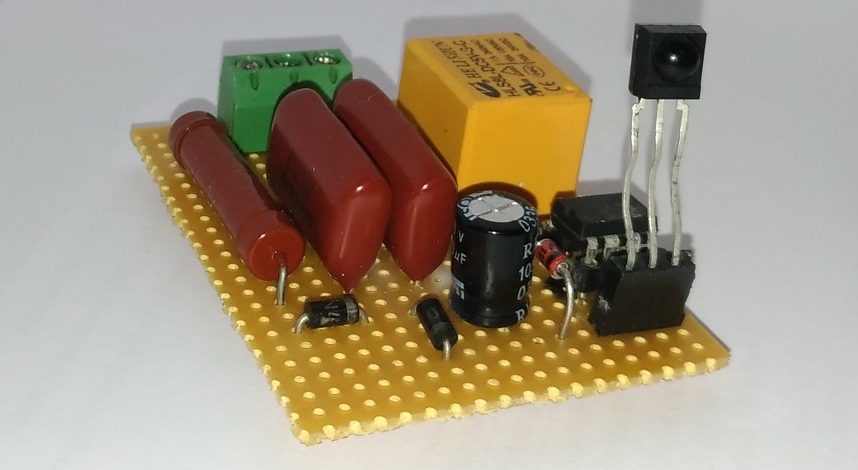
The circuit is quite simple and it’s not necessary to make a PCB to build only one. I used a protoboard and the result is in the photo below. I use it as a normally-closed (NC) light switch.
 Bill of materials
- Microcontroller PIC12F508
- Infrared receiver TSOP2238 (or alternative for desired freq.)
- Resistor 100R/1W+
- 2x Diode 1N4007
- Zener diode 5v1/0.5W+ or 4v7/0.5W+
- Capacitor 2u2F/250VAC+
- Capacitor 1000uF/6V3+
- Relay, 5V/240VAC+ (current depends on the application)
- Reset button, momentary (optional)
- Connectors 250VAC (optional, 1×3 or 1×5)
Circuit diagram
The circuit diagram is given below.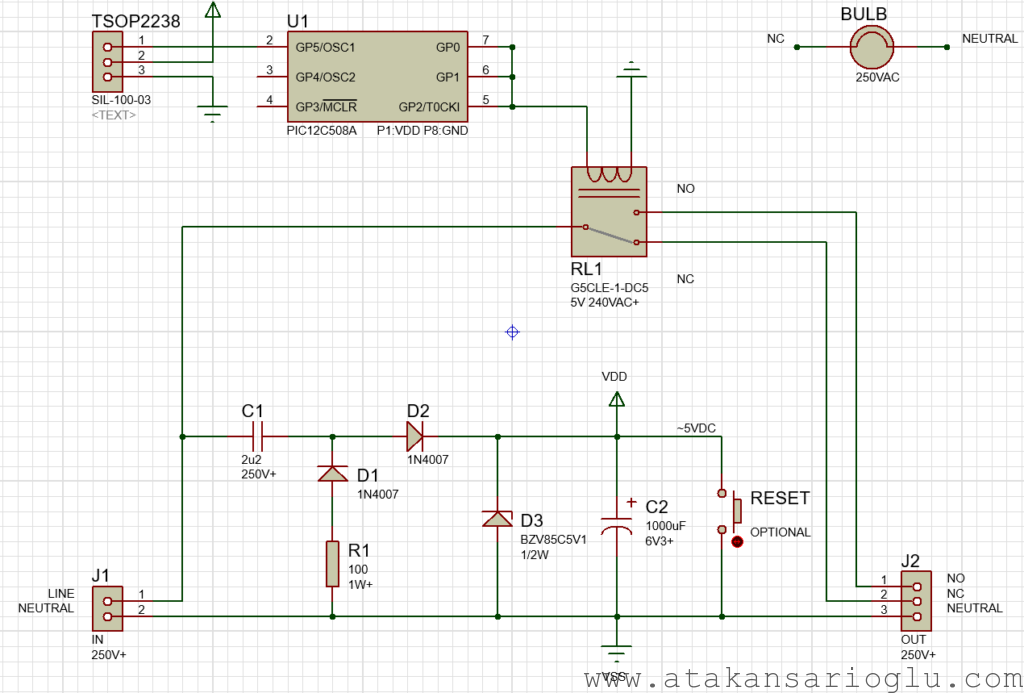 Note that Proteus hides the power pins of the microcontroller in schematic but the required information is given below the microcontroller.
Power stage
This circuit is designed to be connected in series to an AC load, so it has to be powered from AC mains (220VAC-240VAC, 50Hz). Keeping simplicity in mind, a capacitive power supply suits well to this project.
The left-hand side connector J1 is the AC input. On the positive half-cycle, current flows over C1, D2 and charges the capacitor C2 up to zener voltage of D3 (4.7V or 5.1V). On the negative half-cycle, if flows through R1, D1 and C1 without going further into the circuit.
For further reading on capacitive supply Microchip AN954.
SPICE Simulation
The voltage ratings of the components are critical here. In addition, some components must meet specific power rating. The best practice to know the necessary ratings is simulation. Although the component library is not the richest, LTspice is a great tool for analog simulations and it comes for free.
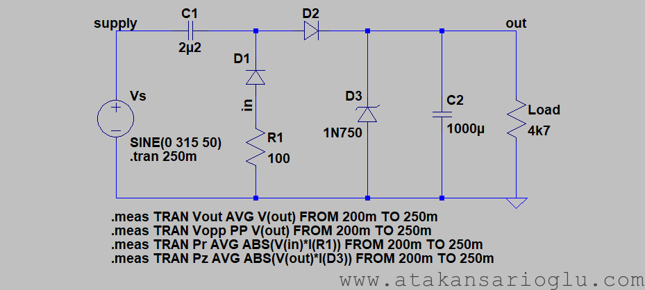 It is wise to analyze the power circuit for two extreme operating regions; low current mode when the relay is off and high current mode when the relay is on. In the simulation green is output voltage, yellow is zener diode power and red is resistor power.
For the low current mode, a current smaller than the sum of supply currents of PIC (0.625mA) and TSOP (0.7mA) should be drawn. 4k7 equivalent load will draw about 1mA and it is reasonable for the simulation.
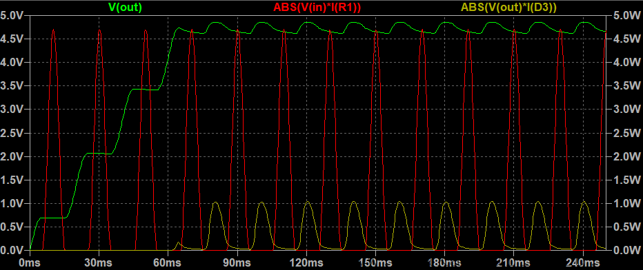 This is the case when the zener diode and the resistor are stressed the most. Observed peak powers are 1.0W for the zener and 4.7W for the resistor. Average powers are measured as 0.35W for the zener diode (should be chosen 0.5W) and 1.15W for the resistor (1.0W is also OK). The average output voltage is 4.73V because in the simulation 4.7V zener is used from LTspice library.
For the high current mode, a current as much as the relay current must be used. The relay has 70R coil and the small currents drawn by the other components can be neglected. So the equivalent load is 70R.
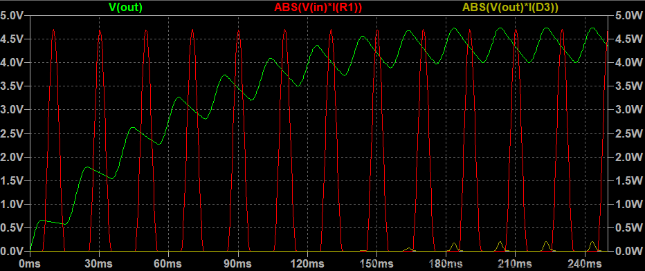 Here the output voltage ripple is around 0.74V and the average output voltage is 4.41V. The values are suitable for both the microcontroller and IR receiver.
Control stage
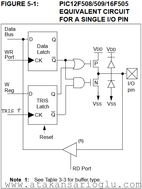
The microcontroller reads the output of the IR receiver over GP5 pin and checks for known patterns. When a match is found, it drivers GP0, GP1 and GP2 to supply enough current to drive the coil of the relay (The maximum current sourced from a pin is 25mA and the relay draws 75mA) There is no need for a reverse diode between the coil pins when using 3 outputs because PIC has already reverse diodes (each capable of clamping 20mA). When a higher demanding relay is connected, GP4 can also be paralleled to those 3 pins but it is not smart to exceed the total current rating for a port which is documented as 75mA.
Electrical Connection
If you want to switch a lamp, then it is better to use the normally-closed (NC) output of the relay. Thus, the light can still be controlled by its own wall switch. If you want to switch a normally-off device, like a heater, prefer the normally-open (NO) output to keep it normally-off. The connection for a lamp is shown below.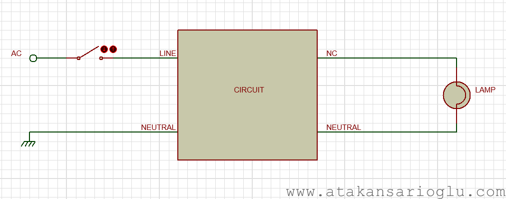
Software
The implementation of the software was the most tricky part because it needed lots of inspection on different remote controllers. And the second challenge was the non-debuggable MCU.
Remote controller signals
I connected TSOP2238 to USBee AX Pro logic analyzer and captured some button signals of different remote controllers with Salaee Logic software.
LG smart TV remote
Vestel radio Remote

 Note that the output of TSOP (seen on the signals above) is inverted (active-low) but the software considers “0” as HIGH and “1” as LOW. So beware of that.
Reader algorithm
By inspecting the signals, an identification method is developed.
First, the start of a message must be detected. This will be done by detecting a long silence (LOW signal). We can consider any LOW signal that is longer than 5ms as an idle (inter-message) space.
|
1 |
TIME_IDLE_us = 5000 |
 Second, to read the message bits we also need to determine (and ignore) the preamble (the leading HIGH-LOW sequence) signal. If the first HIGH signal after the idle period is longer than a threshold, it can be considered as a preamble. This threshold value is 3ms to cover all models.
|
1 |
TIME_PREAMBLE_MIN_us = 3000 |
 Third, in IR language a bit means a HIGH-LOW pair of signals. Each bit will be evaluated as a MARK if the length of LOW part is longer than a threshold, otherwise it will be evaluated as SPACE. This threshold is determined as 1ms.
|
1 |
TIME_MARK_MIN_us = 1000 |
 Finally, when a long silence is detected, the reception will be terminated and the received message is evaluated looking at its MARK and SPACE value. The last threshold that is used to determine that the bit is ended and also the message is ended at the same time. It is 3ms but could be the same as the idle time.
|
1 |
TIME_BITLEN_MAX_us = 3000 |
 Code implementation
The most useful feature of this project is that is can work with any remote controller. To cover that requirement, a memorizing function is needed. The tiny MCU used in this project has only 512B (512x12bits) program space and it’s not possible to implement a fully functional protocol reader algorithm. A universal reader that only records and matches the meaningful IR bits is implemented instead.
Setup and loop
The code is designed with setup and loop functions to make porting to Arduino easier. Setup function sets relay pins as output and TSOP pin as input then starts TMR0 by setting its prescaler.
|
1 2 3 4 5 6 7 8 9 |
void loop(void){ //-- Scheduled tasks. //... //-- Generate time base. while(!mIsTimerExpired()); mResetTimer(); mClearWatchdog(); } |
The loop function runs the tasks and waits for the TMR0 to overflow the designed timeout. The settings in the header sets the looping frequency to 5kHz.
State machine
The state machine loops every 200us (1/5kHz) and is responsible for reading, storing , checking IR signals.
- Init state: creates a long delay if requested, clears the candidate message and resets the counters.
- Sync state: detects a long silence, thus aligns the algorithm to the beginning of a message.
- PreambleWait: detects the HIGH period of the preamble (goes to the next state on the FALLING edge).
- BitWait: waits until the HIGH edge of the first bit.
- BitHigh: waits until the LOW period of the bit, times out if the waiting takes longer than idle time.
- BitLow: measures the length of the LOW period of the bit. If it is longer than the threshold sets the corresponding bit in candidate message. If end-of-message is detected, goes to the Compare state.
- Compare: If the message is the first one after reset, copies the candidate to saved. Otherwise compares the candidate to the saved. If a pattern is not saved yet, it keeps comparing the candidate to the saved. If the same message has been repeating for REPEAT_TO_SAVE times, it stores the message permanently. Once a message is stored, it only checks the candidate and goes to Toggle state on match.
- Toggle: toggles the relay, starts the debounce counter and goes to the Init state.
Source code
main.c file:
|
1 2 3 4 5 6 7 8 9 10 11 12 13 14 15 16 17 18 19 20 21 22 23 24 25 26 27 28 29 30 31 32 33 34 35 36 37 38 39 40 41 42 43 44 45 46 47 48 49 50 51 52 53 54 55 56 57 58 59 60 61 62 63 64 65 66 67 68 69 70 71 72 73 74 75 76 77 78 79 80 81 82 83 84 85 86 87 88 89 90 91 92 93 94 95 96 97 98 99 100 101 102 103 104 105 106 107 108 109 110 111 112 113 114 115 116 117 118 119 120 121 122 123 124 125 126 127 128 129 130 131 132 133 134 135 136 137 138 139 140 141 142 143 144 145 146 147 148 149 150 151 152 153 154 155 156 157 158 159 160 161 162 163 164 165 166 167 168 169 170 171 172 173 174 175 176 177 178 179 180 181 182 183 184 185 186 187 188 189 190 191 192 193 194 195 196 197 198 199 200 201 202 203 204 205 206 207 208 209 210 211 212 213 214 215 216 217 218 219 220 221 222 223 224 225 226 227 228 229 230 231 232 233 234 235 236 237 238 239 240 241 242 243 244 245 246 247 248 249 250 251 252 253 254 255 256 257 258 259 260 261 262 263 264 265 266 267 268 269 270 271 272 273 274 275 276 277 278 279 280 281 282 283 284 285 286 287 288 289 290 291 292 |
/** * @file main.c * @author Atakan S. * @date 01/01/2018 * @version 1.0 * @brief IR remote controlled light switch * * @copyright Copyright (c) 2018 Atakan SARIOGLU * * Permission is hereby granted, free of charge, to any person obtaining a * copy of this software and associated documentation files (the "Software"), * to deal in the Software without restriction, including without limitation * the rights to use, copy, modify, merge, publish, distribute, sublicense, * and/or sell copies of the Software, and to permit persons to whom the * Software is furnished to do so, subject to the following conditions: * * The above copyright notice and this permission notice shall be included in * all copies or substantial portions of the Software. * * THE SOFTWARE IS PROVIDED "AS IS", WITHOUT WARRANTY OF ANY KIND, EXPRESS OR * IMPLIED, INCLUDING BUT NOT LIMITED TO THE WARRANTIES OF MERCHANTABILITY, * FITNESS FOR A PARTICULAR PURPOSE AND NONINFRINGEMENT. IN NO EVENT SHALL THE * AUTHORS OR COPYRIGHT HOLDERS BE LIABLE FOR ANY CLAIM, DAMAGES OR OTHER * LIABILITY, WHETHER IN AN ACTION OF CONTRACT, TORT OR OTHERWISE, ARISING * FROM, OUT OF OR IN CONNECTION WITH THE SOFTWARE OR THE USE OR OTHER * DEALINGS IN THE SOFTWARE. */ #include "main.h" //-- Type definitions typedef enum{ sInit, sSync, sPreambleWait, sBitWait, sBitHigh, sBitLow, sCompare, sToggle, }tStates; typedef struct{ unsigned char State:4; unsigned char isFirstPattern:1; unsigned char isPatternSaved:1; unsigned char reserved:2; }tFlags; //-- Variables unsigned char saved[6] = {0, 0, 0, 0, 0, 0}; unsigned char candidate[6]; unsigned char tickCounter = 0; unsigned char bitCounter = 0; unsigned char repeatCounter = 0; unsigned long int longtermCounter = 0; tFlags flags; void setup(void){ //-- Timer Configuration mStartTimer(); //-- Port Configuration mRelayOff(); mSetupIO(); //-- Initialize the flags. flags.State = sInit; flags.isFirstPattern = TRUE; flags.isPatternSaved = FALSE; } void loop(void){ //-- Scheduled tasks. switch(flags.State){ case sInit: //-- Handle the long term delays. if(longtermCounter){ longtermCounter--; break; } //-- Initialize the candidate. candidate[0]=0; candidate[1]=0; candidate[2]=0; candidate[3]=0; candidate[4]=0; candidate[5]=0; //-- Reset the counters. bitCounter = 0; tickCounter = 0; //-- Go to the synchronization step. flags.State = sSync; break; case sSync: //-- Wait to detect inter-signal space. if(mIsInputLow()){ tickCounter++; }else{ tickCounter = 0; } //-- When the long space detected, start wait for a preamble. if(tickCounter > CNT_IDLE){ tickCounter = 0; flags.State = sPreambleWait; } break; case sPreambleWait: //-- When a falling edge is detected, proceed. if((mIsInputLow()) && (tickCounter > CNT_PREAMBLE_MIN)){ flags.State = sBitWait; tickCounter = 0; break; } //-- Count on high. if(mIsInputHigh()){ tickCounter++; }else{ tickCounter = 0; } break; case sBitWait: //-- When a rising edge is detected, proceed. if(mIsInputHigh()){ flags.State = sBitHigh; tickCounter = 0; break; } //-- Count on low. if(mIsInputLow()){ tickCounter++; }else{ tickCounter = 0; } //-- Check for timeout. if(tickCounter > CNT_IDLE){ flags.State = sInit; } break; case sBitHigh: //-- When a falling edge is detected, proceed. if(mIsInputLow()){ flags.State = sBitLow; tickCounter = 0; break; } //-- Count on high. if(mIsInputHigh()){ tickCounter++; }else{ tickCounter = 0; } //-- Check for timeout. if(tickCounter > CNT_IDLE){ flags.State = sInit; } break; case sBitLow: //-- When a rising edge is detected, proceed. if(mIsInputHigh()){ //-- If the width of the space is long, then it is a mark. if(tickCounter >= CNT_MARK_MIN){ //-- Set the corresponding bit. mSetBit(candidate, bitCounter); } //-- Increase the bit counter. bitCounter++; //-- If the maximum bit amount is reached, ignore the rest. if(bitCounter >= BITNUM_MAX){ //-- Go and check the candidate. flags.State = sCompare; }else{ //-- Else, go detect the next bit. flags.State = sBitHigh; } tickCounter = 0; break; }else{ //-- Count low time. tickCounter++; } //-- If idle then the pattern is completed. if(tickCounter > CNT_BITLEN_MAX){ //-- Check the pattern length. if(bitCounter > MIN_NUMBEROFBITS){ //-- Go and check the candidate. flags.State = sCompare; tickCounter = 0; }else{ //-- Ignore. flags.State = sInit; } } break; case sCompare: //-- If this is the first time, save the received as saved temporarily. if(flags.isFirstPattern){ saved[0]=candidate[0]; saved[1]=candidate[1]; saved[2]=candidate[2]; saved[3]=candidate[3]; saved[4]=candidate[4]; saved[5]=candidate[5]; //-- Clear the flag. flags.isFirstPattern = FALSE; //-- This is the first repeat. repeatCounter = 1; }else{ //-- Compare the candidate to the saved. if(saved[0]==candidate[0] &&saved[1]==candidate[1] &&saved[2]==candidate[2] &&saved[3]==candidate[3] &&saved[4]==candidate[4] &&saved[5]==candidate[5]) { //-- If a saved pattern exists, go toggle the relay on pattern match. if(flags.isPatternSaved){ flags.State = sToggle; tickCounter = 0; break; } //-- If not saved yet, check for the repeat count. else{ //-- Continue. repeatCounter++; if(repeatCounter >= REPEAT_TO_SAVE){ //-- Save. flags.isPatternSaved = TRUE; //-- Toggle. flags.State = sToggle; tickCounter = 0; break; } } }else{ //-- If the first pattern is not repeated, then reset the process. if(!flags.isPatternSaved){ flags.isFirstPattern = TRUE; } //-- Start over the save. repeatCounter = 0; } } //-- Go to the initial state. flags.State = sInit; break; case sToggle: //-- Switch the relay. mRelayToggle(); //-- Setup a debounce time. longtermCounter = CNT_DEBOUNCE; //-- Go to the initial state. flags.State = sInit; break; }// end switch //-- Generate time base. while(!mIsTimerExpired()); mResetTimer(); mClearWatchdog(); } //-- Program void main(void){ // MCU and peripheral settings. setup(); //-- Loop while(1){ // Run loop. loop(); }// end main } |
main.h file:
|
1 2 3 4 5 6 7 8 9 10 11 12 13 14 15 16 17 18 19 20 21 22 23 24 25 26 27 28 29 30 31 32 33 34 35 36 37 38 39 40 41 42 43 44 45 46 47 48 49 50 51 52 53 54 55 56 57 58 59 60 61 62 63 64 65 66 67 68 69 70 71 72 73 74 75 76 77 78 79 80 81 82 83 84 85 86 87 88 89 90 91 92 93 94 95 96 97 98 99 100 101 102 |
/** * @file main.h * @author Atakan S. * @date 01/01/2018 * @version 1.0 * @brief IR remote controlled light switch * * @copyright Copyright (c) 2018 Atakan SARIOGLU * * Permission is hereby granted, free of charge, to any person obtaining a * copy of this software and associated documentation files (the "Software"), * to deal in the Software without restriction, including without limitation * the rights to use, copy, modify, merge, publish, distribute, sublicense, * and/or sell copies of the Software, and to permit persons to whom the * Software is furnished to do so, subject to the following conditions: * * The above copyright notice and this permission notice shall be included in * all copies or substantial portions of the Software. * * THE SOFTWARE IS PROVIDED "AS IS", WITHOUT WARRANTY OF ANY KIND, EXPRESS OR * IMPLIED, INCLUDING BUT NOT LIMITED TO THE WARRANTIES OF MERCHANTABILITY, * FITNESS FOR A PARTICULAR PURPOSE AND NONINFRINGEMENT. IN NO EVENT SHALL THE * AUTHORS OR COPYRIGHT HOLDERS BE LIABLE FOR ANY CLAIM, DAMAGES OR OTHER * LIABILITY, WHETHER IN AN ACTION OF CONTRACT, TORT OR OTHERWISE, ARISING * FROM, OUT OF OR IN CONNECTION WITH THE SOFTWARE OR THE USE OR OTHER * DEALINGS IN THE SOFTWARE. */ #ifndef MAIN_H #define MAIN_H #include #ifdef __CONFIG __CONFIG(INTRC/*XT*/& WDTEN/*WDTDIS*/& PROTECT/*UNPROTECT*/& /*MCLREN*/MCLRDIS); #else #pragma config OSC = IntRC/*XT*/, WDT = ON, MCLRE = OFF, CP = ON #endif //-- Definitions #define TRUE 1 #define FALSE 0 #define TIMEBASE_250Hz 250 #define TIMEBASE_500Hz 125 #define TIMEBASE_1kHz 125 #define TIMEBASE_2kHz 125 #define TIMEBASE_4kHz 125 #define TIMEBASE_5kHz 100 #define TIMEBASE_10kHz 50 #define TIMEBASE_PS_250Hz 0b011 #define TIMEBASE_PS_500Hz 0b011 #define TIMEBASE_PS_1kHz 0b010 #define TIMEBASE_PS_2kHz 0b001 #define TIMEBASE_PS_4kHz 0b000 #define TIMEBASE_PS_5kHz 0b000 #define TIMEBASE_PS_10kHz 0b000 //-- Board Settings #define TRIS_SETTING 0x28 // GP5 is input, MCLR is always input. #define PIN_RELAY GPIO #define PIN_DETECT GP5 #define RELAY_ON 0xFF #define RELAY_OFF 0x00 #define PIN_DETECT_HIGH 0 // TSOP is active-low. #define PIN_DETECT_LOW 1 // TSOP is active-low. //-- Application Settings #define TIMEBASE_Hz 5000UL//-- Under 4kHz is not supported. #define TIMEBASE_us (1000000UL/TIMEBASE_Hz) #define TIMEBASE_CNT TIMEBASE_5kHz//-- Same as TIMEBASE_Hz. #define TIMEBASE_PS TIMEBASE_PS_5kHz #define TIME_IDLE_us ( 5000UL) #define TIME_PREAMBLE_MIN_us ( 3000UL) #define TIME_MARK_MIN_us ( 1000UL) #define TIME_BITLEN_MAX_us ( 3000UL) #define TIME_DEBOUNCE_us (1500000UL) #define BITNUM_MAX 48 #define REPEAT_TO_SAVE 10 #define MIN_NUMBEROFBITS 4 //-- Compile-time calculations. #define CNT_IDLE (TIME_IDLE_us/TIMEBASE_us) #define CNT_PREAMBLE_MIN (TIME_PREAMBLE_MIN_us/TIMEBASE_us) #define CNT_MARK_MIN (TIME_MARK_MIN_us/TIMEBASE_us) #define CNT_BITLEN_MAX (TIME_BITLEN_MAX_us/TIMEBASE_us) #define CNT_DEBOUNCE (TIME_DEBOUNCE_us/TIMEBASE_us) //-- Macros #define mClearWatchdog() asm("CLRWDT"); #define mIsInputHigh() (PIN_DETECT == PIN_DETECT_HIGH) #define mIsInputLow() (PIN_DETECT == PIN_DETECT_LOW) #define mRelayOn() PIN_RELAY=RELAY_ON; #define mRelayOff() PIN_RELAY=RELAY_OFF; #define mRelayToggle() PIN_RELAY=~PIN_RELAY; #define mSetupIO() TRIS=TRIS_SETTING; #define mStartTimer() OPTION=0b11000000+TIMEBASE_PS;TMR0=TIMEBASE_CNT; #define mResetTimer() TMR0-=TIMEBASE_CNT; #define mIsTimerExpired() (TMR0>=TIMEBASE_CNT) #define mSetBit(var, bitnum) {*((char*)var + (bitnum>>3)) |= (1 << (bitnum & 0x07));} #define mClrBit(var, bitnum) {*((char*)var + (bitnum>>3)) &= (1 << (bitnum & 0x07)) ^ 0xFF;} #endif /* MAIN_H */ |
Compilation
The source code can be compiled using MPLAB X + XC8 (tried with v4.05 and v1.44) or stress-free online compiler MPLAB-Xpress. If you think you are too lazy to compile yourself, the hex file is here.
Final Words
The project is designed to be universal but there are always some exceptions. Everything is tested and works fine with the remote controller types listed above. When i have another remote controller i will also make the necessary tests with it immediately.
Due to the limitations of the MCU, a perfect software that covers every detail couldn’t be provided. It is also possible to switch to an Arduino UNO with the same logic and see what could be improved.
Have fun 😉

